The banner above is an advertisment - if it asks you to download software, please ignore.
Site News - 4/9 Saab Owners' Convention Day Pass Raffle | 3/26 M Car Covers (by State of Nine)

Overview

Getting Started

Project Outline

Parts Checklist

Preparation

Engine Removal

Transmission Swap


Transmission Swap

 
Borg-Warner Type 37 Automatic transmission.

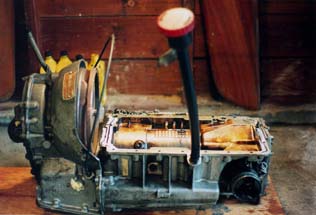
All major engine components should be cleaned and degreased.

Step 1. Separate engine from the automatic transmission.

Remove the plastic cover that surrounds the torque converter housing.On turbo models, remove the turbocharger support bracket.

Remove the bolts that hold the torque converter to the driveplate by putting a socket wrench with an extender bar through the access hole on the front plate of the engine. See Illustration.

Remove all of the engine to transmission bolts.

Attach an engine hoist to the engine lifting lugs. It is important that the engine is lifted perfectly straight. If the hoist does not lift the engine perfectly straight, the engine will bind to the transmission and it will not separate. If at first the engine does not separate from the transmission, it may be necessary to carefully pry the engine from the transmission.

Step 2. Preparing the engine for conversion

  • Replace engine oil pickup tube with one from a manual 900 engine. Two bolts connect the tube to the engine. See Illustration. The tube used as a replacement should be clean with a good o-ring on the end.
  • Remove converter driveplate. It will be necessary to prevent the engine from turning while loosening these bolts. A small block of wood inserted between one of the engine 's connecting rods and the outer wall of the engine block works well.
  • Install the 900 flywheel. There is a dowel on the end of the crankshaft that only allows it to fit one way. It is important to use threadlock on the flywheel bolts. 17mm bolt - 44 ft/LB 19mm bolt - 63 ft/lb.
 
Step 3. Mating the engine to the manual transmission.
  • Clean mating surfaces of both engine and transmission. Also clean thoroughly the top cavity of the transmission as this is the oil sump for the engine.
  • Place a new engine to transmission gasket on the transmission, squeeze a bead of Loctite 518 gasket sealant both on the front and rear of the gasket in the grooves. This is illustrated in the Bentley manual.
  • Attach the engine to an engine hoist such that the engine is hangs perfectly parallel to the transmission. Lower the engine slowly. There are pegs in the engine that will help locate the engine properly. Once the engine is seated on the transmission, begin threading the engine to transmission bolts. Do not tighten any of them until all bolts are threaded. If the bolt holes are not lined up exactly, the engine can be shifted slightly using the hoist until all bolts are seated. There are six bolts that will require thread sealing compound. These are illustrated in the shop manual.
  • Torque the engine-to-transmission bolts to 18-ft/lbs

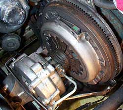
Step 4. Installing the Clutch

Installed 900 clutch assembly

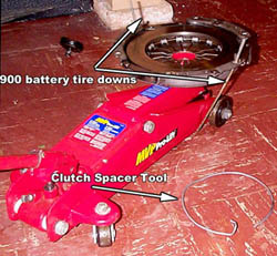
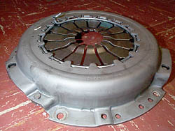
The clutch diaphragm spring assembly, clutch disc, throw-out bearing and slave cylinder are installed between the engine flywheel and transmission final gear housing as a unit. In order to get the clearance necessary for these three components to fit, the diaphragm spring must be compressed and held in the compressed state by means of a special spacer tool.

The spacer tool is a metal dowel bent into a circle which is inserted between the spring fingers and the diaphragm body. It can be fashioned from an old bucket handle with a pair of pliers and a little patience.

Using a hydraulic jack and a pair of battery hold-down rods to compress the spring diaphragm assembly so the spacer tool can be inserted.

Compressing the diaphragm spring is more of a challenge. This author used a hydraulic floor jack, and a pair of battery hold-down rods to compress the spring. A bottle jack can also be employed for this task.

  1. Compress the spring fingers on the diaphragm assembly and insert the special spacer tool.
  2. Mount the throw-out bearing onto the slave cylinder shaft.
  3. While holding the slave cylinder/T.O bearing against the spring fingers, and the spring diaphragm unit against the clutch disc, place all three components between the flywheel and transmission housing. The spring diaphragm should seat itself onto the small dowels in the flywheel. Make sure that the bolts holes for the slave cylinder line up properly. Insert two of the diaphragm-to-flywheel bolts loosely o keep the assembly in place.
    Clutch spacer tool properly installed.
  4. Lubricate the splines on the input shaft with grease and insert it through the transmission casing and spring diaphragm assembly until it engages the splined center of the clutch disc. Using a plastic hammer, tap it lightly until it seats itself fully.
  5. Install the slave cylinder screws using thread sealer.
  6. Install and tighten the remaining spring diaphragm assembly-to-flywheel bolts.
  7. Install the plastic "propeller" bolt to the end of the input shaft. Replace the input shaft cover and cover spring