1985-1998 [Subscribe to Daily Digest] |
 Members do not see ads below this line. - Help Keep This Site Online - Signup
Greetings friends,
My driver's side doorlock failed recently, so I worked out a means to have a remote keyless entry/alarm control. Please feel free to email me with any questions.
Ben
-------------------------------------------------------------------------
Report on installing remote alarm/locking on a 91 Saab 9kT.
-------------------------------------------------------------------------
When completed, I have a keyless remote entry and alarm. All the doors now lock centrally; the driver�s side (d-side) lock no longer controls the entire car. Central locking is controlled from the key-fob, though there is a poorly documented feature on the remote electronic control unit (ECU) about "locking by ignition" which might lock the doors when you start the car. The keyfob has buttons for lock, unlock and a 3rd that intended to unlock the trunk, but this button is now the alarm-arming switch. (See �Alternate Possibilities� #1, below)
You will get the colors/pins of the remote ECU with its manual, and you should obtain the same for the Saab from a suitable source. If you need a source, I recommend http://www.alldatadiy.com, they cost $20/year/car and are quite good. (That and a Haynes book from England and you'll be in good shape)
This set of directions is deliberately spare, so if you find them too limited, please do not to try this yourself. For a variety of reasons, this is not intended to be a step-by-step manual, but rather a guide to the objectives.
In hindsight, this is not a �car hacking� project except for the incurable. (yep, that�d be me!) It is just a bit more frustrating than a typical hack is worth. (Consider: Unless you�re rich in ScotchLoks, you�ll be trying to in-line strip wires under the d-side dashboard with absolutely no slack, above the clutch. If this doesn�t make a clear image, trust me, this is a nasty job that is prone to a one-slip accident with nightmarish results.)
However, if your d-side lock has failed in some way, then this job is cheap and I think no harder than replacing all of the locks. So as a complete repair by an unusual method, this job is a winner. And this conclusion applies to partial-failures of the d-side door lock, for example, loss of alarm control.
Equipment----------------------------------------------------------------JC Whitney's Remote Keyless System, "38zx2164y" $39.99.
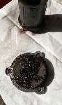
A lockmotor, in my case from an 86 900s passenger-side door.
Two diodes, I just nabbed a pair from Radio Shack for about $2. (I think they're 3 amps, 50v: hefty, but hardly special.)
Four pieces of wire, about 6 to 10 feet long, medium guage. I actually used 16guage house wire. (THHN insulation)
Preparations--------------------------------------------------------------Make sure you alarm's LED is working properly; life is much easier when that little blinker is KNOWN to be working.
Make sure your alarm is working properly. If you are in doubt, I recommend forgetting about it. Troubleshooting the installation AND the alarm at the same time is quite difficult. If necessary, open the d-side door and cycle-test the alarm by using a clip lead on the pins of the lockswitch�s wiring harness.
Power the Remote ECU from the Alarm ECU�s feed.
Ground remote ECU�s ground supply, lock polarity, and trunk polarity to the Alarm ECU�s ground. (Those polarity thingies are explained in the Remote ECU�s manual)
Overview-----------------------------------------------------------------(A) Install a used lockmotor in the d-side door, (see "Alternate Possibilities� #2, below.)
(B) Get the remote ECU to control the existing central locking.
© Then add the d-side door lockmotor to the central locking system by sacrificing the wiring to the keyswitch to power the lockmotor.
(D)I then added the alarm functions to the remote ECU. (I had to reverse a little of © to install the diodes. If you just connect the locking ECU�s inputs to the Alarm ECU�s inputs, the alarm will remain perpetually disarmed.)
Phase 1: Install a lockmotor in the d-side door.-------------------------
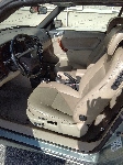
I used the lockmotor from my 86 900s passenger�s side (p-side) door. The lockmotor is an exact replacement for the lockswitch, so you can simply swap them and keep the switch nearby in case you need it for testing, or want to abort the project and restore original function. Note that from this point on, the lockswitch must be electrically disconnected.
Phase 2: Getting the central locking under remote control.---------------NOTE: I recommend ScotchLok connectors for all splices at the locking ECU, because the wiring is very short and it is difficult to work under the d-side dash.
If you have left your lockswitch in place, (see �Alternate Possibilities� #3, below) then please disonnect its plug now. If the switch is plugged in, I found the locking ECU got confused every now and then.
Run two wires from the locking ECU (d-side) to the alarm/remote ECUs (p-side.) Connect the remote ECU�s LOCK wire to the GREEN wire of the locking ECU, and the UNLOCK wire to the RED wire of the locking ECU. DO NOT MAKE THESE CONNECTIONS PERMANENT, if you will be controlling the alarm with the remote ECU.
Run a test. You should get all doors locking except the d-side. This should�ve been an easy first success.
Phase 3: Powering up the d-side lockmotor.--------------------------------
NOTE: I recommend ScotchLok connectors for all splices at the locking ECU, because the wiring is very short and it is difficult to work under the d-side dash.
Run two MORE wires from the Lock ECU to the p-side under dash area. Connect them to the lock ECU�s outputs. These will power the new lockmotor, but first we have to get them to the p-side dash, where the wiring is into the door.
On the p-side, connect these wires to the cut ends of the original equipment wiring that leads back to the d-side door keyswitch. (see �Alternate Possibilities� #4, below)
You now have made two of the keyswitch wires in the d-side door into an OUTPUT from the locking ECU. Some guesswork may come in here, connect these two wires to the lockmotor. Test it, and make the connection to the lockmotor permanent when you are satisfied the polarity is right.
Phase 4: adding the Alarm function to the remote ECU�s outputs.----------
Break the connections from the Remote ECU to those wires you ran to the Lock ECU�s INPUTS. Put the diodes in here, the end of the cylindrical diodes with a silver band should be AWAY from the Lock ECU, and TOWARDS the remote ECU. These diodes prevent the Lock ECU from appearing like a sink to the Alarm ECU, which will instantly disarm the alarm.
Now, attach the Remote ECU�s UNLOCK output and the Alarm ECU�s DISARM input together, and put them both on the free end of the diode on the Lock ECU�s UNLOCK input.
Attach the Remote ECU�s LOCK output to the free end of the Lock ECU�s LOCK input diode.
Wait, your asking, what about the Alarm ECU�s ARM input? Connect it to the Remote ECU�s �Trunk Unlock� output.
Now, you have the Lock ECU�s inputs isolated by diodes, and connected to the Remote ECU as in Phase 2.
The Alarm ECU�s inputs are connected to the remote. (Disarm input to Unlock output, and Arm input to Trunk Unlock output.)
You should now be ready for a test. Close ALL doors, trunk, and hood. Pressing LOCK will lock all the doors, as in Phase 3. Pressing UNLOCK�oh fine, you get that part. Now, LOCK the doors. NOW, press the 3rd switch. (�Not the THIRD switch?!�) You�ll notice a little lag before hearing the faint click of a relay in the Remote ECU. Release and wait the prerequisite eternity for the alarm to come on. Once the alarm is fully armed (you DID make sure your alarm�s LED is working before, right?), press the UNLOCK switch. Presto, doors open and alarm disarms. Is this cool or what?!
Want the piece de resistance? LOCK the doors, and press AND HOLD the Trunk Lock button for the requisite 10 seconds or so. <chirp> alarm armed IN TRANSPORT MODE! I nearly cried when this finally worked.
Final Project Notes------------------------------------------------------
I would recommend double-stick taping the remote ECU to the top of the alarm ECU, they�ll fit nicely, and it�ll make it easy to find. Also, take the time to tape things up thoroughly, my setup acted flaky on my road test, and I think it was because something bare brushed something grounded.
Alternate Possibilities--------------------------------------------------
#1::: If you�re happy with the factory central locking system, it is very easy to put this remote in simply to arm/disarm the alarm. (You will not need the diodes, but you will need to continue to use the Trunk Unlock button for arming, since it is the ONLY remote ECU function that stays on as long as you hold the button down. (There is a slight delay before this function comes on, I find myself counting to five briskly to assure an arm.) Remember that you need a holding function here so you can enter �transport� mode, or to calibrate the alarm. (Sorry, I hate it too, but sacrifincg access to transport/calibration is a high price to pay for better looks.)
#2::: My D-side lockswitch is STILL installed. I glued the switch to the lockmotor, and made an H-shaped piece of metal to tie the two together mechanically. This is UNNECSSARY, but I was waiting for parts, so I used the car for two weeks with the lockmotor installed but inert. If you choose to "siamese twin" them like I did, you'll want to make the lockmotor the principal connection to the locking system mechanically. The h-shaped piece of metal ties the switch plunger to the motor plunger, allowing the motor to still hook into the locking system. The switch is still in the door now, with the h-shaped piece of metal removed and stored securely inside the door, also the electrical connector is securely disconnected.
#3::: Lock motor and switch in one body: possibly someone out there who knows can let us in on the later models with central locking/remote locking if there is an all-in-one unit installed. It would eliminate Phase 1.
#4::: The keyswitch wires in the d-side door are really marginally sized to power the lockmotor (I'll let you know when it hits -20F this winter). If you can sacrifice the original function of the central locking system (EG: If your lockswitch has failed) then you could substitute those control wires. This would simplify the project by requiring only ONE RUN of wires from the d-side dashboard to the p-side. (from the Lock ECU inputs to the Remote ECU outputs.) Simply cutting the lock ECU inputs, and splicing the door wire feeds to the outputs will take care of the in-door wiring for the lock motor. Then the little wire-stubs of the Lock ECU inputs (you did leave them long enough to do this, right?) are connected to that one-and-only cross car wiring to reach the remote ECU outputs. This might be quite elegant.
My Glossary:-------------------------------------------------------------
D-side: Driver�s side. (US)
P-side: Passenger�s side (US)
Keyswitch: the switch that is part of the driver�s side (d-side) lock cylinder. It is connected by 3 very fine-gauged wires going to a square (4-place) connector.
Lockswitch: the bulky switch that is connected mechanically to the d-side door�s locking hardware. It has three medium-guage wires on its rectangular connector.
Lockmotor: the bulky motor that is in all the doors BUT the d-side, it serves to push/pull each door�s locking hardware in almost exactly the same way you do by hand.
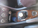
Lock ECU: The electronic control unit for the central locking system. D-side, above the clutch, on the forward side of the inverted tray, held in place by a chrome-plated u-clip. Spotting the clip is easier than spotting the ECU. By the way, there�s no �e� in this ECU, it seems to be nothing more than a pair of relays.
Alarm ECU: The alarm�s electronic control unit. Think of it as being immediately under the ventilator by the p-side door. My �91 has the improved ECU from the �93s. If yours fails, I strongly recommend paying the extra for this �yellow box� model, it is immensely smarter than the old one. See Townsend�s site for more info on these modules.
Remote ECU: the remote control electronic control unit. This is what you buy from JC Whitney.
ScotchLok: 3M�s brand of in-line wire splicers. It is moderately critical to have the correct size for the wire you�ll be splicing, so open things up, survey the wiring, and then go buy them.
Third Switch: See �Young Frankenstein� by Mel Brooks.
No Site Registration is Required to Post - Site Membership is optional (Member Features List), but helps to keep the site online
for all Saabers. If the site helps you, please consider helping the site by becoming a member.
 |
 |
 |
 |
 |